Acoustics and Electroacoustics for Ceramics
( The full text of this paper will be appearing shortly in a major ceramics magazine )
Determination of both the particle size distribution and the zeta potential of ceramic slurries is of key importance in optimizing performance. The particle size of the slip is closely related to inhomogeneities, which in turn relate to fracture origins as well as shape distortion/cracking during drying, pyrolysis and sintering. Furthermore, the zeta potential of the slurry particulates can be used as a tool for optimizing chemical dosage to achieve the desired colloid stability and size distribution.
Traditional measurements of particle size and zeta potential usually involve light scattering or sedimentation techniques and require extreme dilution of the ceramic slip. This dilution step often changes both the size distribution and the zeta potential of the sample, thereby distorting the very information being sought. Characterizing the concentrated sample directly would allow us to realistically judge the true agglomeration status of the slip and to optimize the dosage of various chemical additives in situ. In contrast, measurements of the diluted samples with traditional methods often reveal only the primary size of the raw materials since the usual sample preparation steps of dilution, chemical modification, stirring and perhaps even sonication have destroyed most of the useful information about the original slurry.
Two complementary ultrasonic techniques have now been developed which allow such direct measurement of ceramic slurries, as is, without any sample preparation or dilution. (1,9)
Acoustic spectroscopy measures the attenuation and sound speed of ultrasound pulses as they pass through concentrated slurries. The measurements are made over a wide range of frequencies and the resulting spectra are used to calculate the particle size distribution over a range from 10 nanometers to more than 10 micrometers.
Electroacoustic spectroscopy measures the interaction of electric and acoustic fields from which the zeta potential can be determined.
Both spectrometers are now commercially available, either separately, or combined in a single instrument such as the Dispersion Technology DT1200. These methods provide accuracy and precision of a few percent on samples as small as 30 to 100 ml, and in just a few minutes time. A unique feature is the ability to determine separate particle size distributions for mixed systems such as alumina/zirconia slurries. Automated titration equipment invokes changes in agglomeration as a function of pH or dispersant dosage, which allows the ceramic processor to optimize performance at minimum chemical cost and operate the process under the best conditions.
Although much of the experimental method is new, the overall approach is based on a well-established scientific background (2,3,4,5,6). In both methods the interaction of sound with the dispersed particles provides useful information. However, the driving force and measured parameters are different in each case.
Acoustic Spectroscopy Basics
For acoustic spectroscopy pulses of sound are applied to the test slurry and the instrument measures the attenuation and propagation velocity of the sound for a wide range of ultrasonic frequencies, typically 1 to 100 MHz. Simply put: sound in – sound out. A simplified block diagram is shown in Figure 1. The gap between the transmitting and receiving transducer is computer controlled by means of a stepping motor. The signal level at the output transducer is measured for a set of discrete frequencies and gaps. The rate of change in the signal level with gap, expressed in dB/cm, corresponds to the attenuation due to losses in the colloid. These losses arise from several mechanisms including scattering, viscous, and thermal loss (4). A key part of the method is a predictive theory which allows the instrument to calculate the expected attenuation for a given size distribution, taking into account these various loss mechanisms. The particle size distribution is computed by finding the distribution that minimizes the difference between the acoustic spectrum computed from theory and the experimental spectrum. The fitting error between theory and experiment provides a confidence factor for the final result. The software will provide either log normal or bimodal distributions, as necessary to best match theory to experiment consistent with the experimental errors. The colloid attenuation shown in the figures, which follow, is expressed in dB/cm/MHz.
One very attractive feature of this acoustic technique is that the colloid attenuation depends only on the rate of change of signal with changes in the gap and is independent of the signal level itself. As a result, acoustic spectroscopy, unlike optical methods, is inherently very robust and not sensitive to fouling or contamination of the acoustic transducers and therefore very suitable for online production monitoring and control
Electroacoustic Spectroscopy Basics
In contrast to the acoustic method, which is purely acoustic, electroacoustic spectroscopy as the name suggests is half acoustic and half electric. It probes the interaction between acoustic and electric fields. There are two ways to do this. In the first case, the slurry is excited with pulses of ultrasound. The small fluid displacements produced by this sound wave causes small periodic displacements of the electrical double-layer surrounding each charged particle. This distortion produces an electric field, which can be sensed by an antenna immersed in the slurry to record the short circuit colloid vibration current (CVI). A simplified block diagram is shown in Figure 2. Simply put: sound in – electrical signal out
In principle, one can do the reverse experiment, i.e. excite the slurry with an electric field, which then interacts with the particles to create an acoustic response. This reverse technique is usually referred to as Electrokinetic Sonic Amplitude (ESA). Simply put: electrical signal in – sound out.
Although the normal and reverse method appear similar, the theory for the more conventional forward CVI technique has been more extensively developed and is valid for concentrations up to 50 vol. %. (8) In contrast, the theory for the reverse ESA technique to date is valid only for volume fractions less than 5% and relies on empirical corrections for measurement of real-world slurries. (7)
Best of both worlds: Combination of methods
The measured electroacoustic spectrum for a given slurry contains information about both the particle size and zeta potential. At first blush, this appears to make electroacoustic spectra very attractive for providing simultaneous measurement of both parameters from a single set of data. In practice, however, there are several disadvantages to using only electroacoustic data for such complex particle characterization. First, the electroacoustic spectra can only be measured for charged particles. Second, the desired particle size distribution and zeta potential information can only be deduced from this spectra for a limited range of conductivity and only if one makes some rather restrictive assumptions about the nature of the double layer surrounding the particle. Third, the uncertainties in the model and the underlying theory makes it impossible to obtain any more detailed information than a simple lognormal approximation to the actual distribution.
In contrast, the acoustic spectra for a given slurry is unaffected by either the slurry conductivity or the charge on the particles. On the down side, it is not possible to obtain zeta potential from the acoustic spectra. On the bright side, however, we can obtain size data for any conductivity, and even for uncharged particles. The acoustic spectra depend only on the size distribution and the slurry concentration. Therefore, one might reasonably expect that the particle size derived from acoustic spectroscopy to be more accurate than that obtained from the electroacoustic spectra.
In practice, one finds that the most reliable and versatile measurements are obtained by incorporating results from both acoustic and electroacoustic spectra. The particle size is best derived from the acoustic spectra. This size data is valid for any conductivity, whether the particles are charged or not. The electroacoustic spectra is then used primarily for calculating the zeta potential, however, a particle size determined from this data can be used as a consistency test to see how well the actual colloid fits the assumptions of the model. This high degree of cross-checking between the two independent techniques provides a high confidence in the quality of the data. Such confidence checks are often missing in some “black box” instruments, which do not have the advantage of redundant sources of data.
Ceramic Applications
Acoustic spectroscopy can provide accurate particle size data even in concentrated slurries. Figure 3 A shows the measured particle size distribution for four different alumina slurries. Figure 3B shows the experimental attenuation for these samples along with the best-fit theoretical curve for the measured size distribution. Figure 3C gives a comparison of the measured particle size with the manufacturer’s data derived from traditional methods. The agreement between acoustic and traditional methods is quite good because care was taken in formulating the concentrated dispersion with an optimum level of surfactant to insure good dispersion of the primary particles. In many real-world cases, the final dispersant dose may have been simply extrapolated from very dilute measurements and one may obtain a larger particle size in the actual slurry than predicted from these dilute measurements of the raw materials. It is almost always better to characterize the particle size of the slurry. When this does not compare with dilute measurements one needs to examine whether the chemical formulation is adequate.
Acoustic spectroscopy is applicable to virtually all ceramic materials. Figure 4 shows typical particle size distributions for a variety of commonly used ceramic materials.
For many applications it is important to recognize particle size sub-populations in the final slurry. Such bimodal distributions might result from agglomeration of primary particles caused by non-optimum dispersant addition, or in the following example, from an intentional addition of a second size fraction. Figure 5A shows the acoustic attenuation spectra for three 10 volume % alumina slurries: a 0.36 micrometer sample, a 2 micrometer sample, and a 1:1 mix of the two. The theoretical spectra fit quite precisely the experimental data giving high confidence in the results. Figure 5B shows the resulting size distributions for the two single component slurries (blue and black curves) as well as the bimodal distribution for the mixed slurry (red curve).
In other applications it is important to be able to detect a very small sub-population of a few large aggregate particles mixed with a large number of much smaller particles. For example, chemical mechanical polishing (CMP) slurries are used in the semiconductor industry to planarize silicon wafers at various steps in the production of computer chips. One large aggregate particle can cause a major scratch and destroy circuit performance. Figure 6 shows the ability of acoustic spectroscopy to detect one relatively large 1 micron particle per million smaller 300 nm particles.
In many ceramic applications the ceramic slip is actually a mixture of more than one solid component. Traditional optical or sedimentation techniques can not provide correct interpretation of such mixtures and typically assume that all particles have a common set of physical properties. In contrast, commercially available software for acoustic spectroscopy has evolved to the point that allows the specification of at least two classes of disperse particles. For example, Figure 7 shows an example of a mixed system of alumina and zirconia particles. Figure 7A shows the attenuation spectra for three 5 volume % slurries: a 2 micrometer single component alumina, a 0.3 micrometer single component zirconia, and a 1:1 mix of the two ingredients. Again, the theoretical spectra fit the experimental data quite precisely giving high confidence in the results. Figure 7B shows the resulting single mode particle size distribution for each oxide measured separately, as well as two separate single mode distributions measured for each component in the mixed slurry system.
It is not always appreciated that the particle size distribution of a slurry is not simply a function of the primary size of the constituent ingredients, but instead is a result of many complex chemical and mechanical operations on the system. The zeta potential of the system is one parameter that can be used to investigate this complex relationship. Figure 8 compares zeta potential data for a typical rutile and alumina sample using electroacoustic data. The pH at which the zeta potential goes to zero is referred to as the isoelectric pH. Different materials may have quite different isoelectric points as is evident from this figure. If we desire good stability, then we need to operate far enough from the isoelectric point to achieve a zeta potential in excess of say 20-30 mV, either plus or minus. For the alumina shown this would suggest that to obtain optimum stability for this alumina, one should adjust the pH to avoid the pH range between 8 and 11 where the zeta potential is less than 20 mV. This complex relationship between zeta potential and particle size distribution can be easily understood using acoustic spectroscopy. Figure 9A shows the size distribution for this same alumina at a pH of 4.0. In contrast Figure 9B shows the size distribution for the same sample where the pH was adjusted to 9.0, very close to the isoelectric point.
In the real world, the situation is sometimes even more complex. The particle size and zeta potential is not just a function of the final chemical state of the system, but may depend also on the history of how the system reached this state. In other words, the complete history of the sample may be important as is illustrated in Figure 10, a case history of a plant manufacturing silicon nitride. The red curve shows the zeta potential as the pH is decreased to an acid condition. From just this data alone one would think that a pH of 7- 8 would provide adequate zeta potential for stability. However, operating experience in the plant indicated otherwise. A clue to the problem was found by reversing the titration towards more alkaline conditions. The reverse titration, shown by the blue curve, revealed that the isoelectric point decreased by 2 pH units after the slurry was exposed to this acid condition. Investigation of plant operations showed that the slurry processing normally included such an acid wash. In order to obtain adequate stability following this acid condition, the data suggests that the process pH must be readjusted to a point either significantly below or above this new isoelectric point. But how can we explain this dramatic shift in the isoelectric point? The explanation is actually quite simple. The initial slurry had a very small level of contamination, which was insignificant in terms of the overall stability of the system. However, under acid conditions this minor component dissolved. Upon subsequent change to more alkaline conditions, this dissolved material re-precipitated on the surface of the major silicon nitride component. Now this minor component, although present only in seemingly insignificant quantity, nevertheless dominated the surface chemistry of the silicon nitride material. By realizing that the final state is dependent on the history of the sample the process could be modified to accommodate this change.
In summary, acoustic and electroacoustic spectroscopy provide not only a useful method for characterizing the final aggregative state of a ceramic slip, but also an important tool to help us understand, optimize, and control this state. These acoustic techniques will become more widely adopted as process engineers and researchers realize the benefits of supplementing dilute measurement of raw materials with actual measurements of the final concentrated product.
References
World WideWeb Site, URL=https://dispersion.com
Dukhin, A.S. and Goetz, P.J., “Acoustic Spectroscopy for Concentrated Polydisperse Colloids with High Density Contrast”, Langmuir, vol.12, No. 21, pp. 4987-4997 (1996).
Dukhin, A.S., Goetz, P.J. and Hamlet, C.W., “Acoustic Spectroscopy for Concentrated Polydisperse Colloids with Low Density Contrast”, Langmuir, 12, No. 21, 4998-5004 (1996).
Dukhin, A.S. and Goetz, P.J., “Acoustic and Electroacoustic Spectroscopy ”, Langmuir, vol. 12, No. 19, pp. 4336-4344, (1996).
Dukhin, A.S. and Goetz, P.J., “Characterization of Aggregation Phenomena by means of Acoustic and Electroacoustic Spectroscopy ”, Colloids and Surfaces, vol. 144, pp. 49-58, (1998).
McClements, D.J. “Ultrasonic Characterization of Emulsions and Suspensions”, Adv. in Colloid and Interface Sci., vol. 37, pp. 33-72 (1991)
Hunter, R.J. “Review. Recent developments in the electroacoustic characterization of colloidal suspensions and emulsions”, Colloids and Surfaces, 141, 37-65 (1998).
Dukhin, A.S., Oshima,H., Shilov, V.N.,Goetz, P.J., “Electroacoustics for Concentrated Dispersions”, Langmuir, accepted for publication
Ultrasonic and Dielectric Characterization Techniques for Suspended Particulates, Edited by V.A. Hackley and J. Texter, American Ceramic Society, Westerville, OH, 1998.
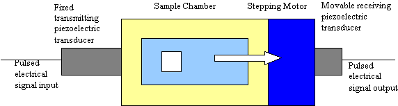
Figure 1: Block Diagram of Acoustic Spectrometer – The transmit transducer provides pulsed
ultrasound excitation of the slurry over a wide range of frequency. Attenuation is measured from decrease
n received signal with increasing gap. Sound speed is determined from increase in arrival time with gap.
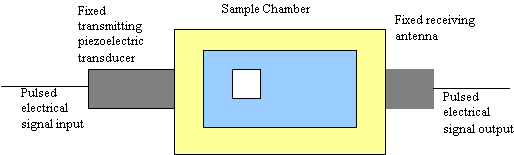
Figure 2: Block Diagram of an Electroacoustic Spectrometer– The transmit transducer provides pulsed ultrasound
excitation of the slurry over wide range of frequency. Receiving antenna measures resulting colloid vibration current,
from which zeta potential is calculated.
Figure 3a: Measured particle size distributions for four Sumitomo aluminas demonstrates the wide particle size range
capability of acoustic spectroscopy and the ability to provide quality control of a wide range of raw materials
Figure 3b: Acoustic Spectra for same four aluminas fit precisely with theoretical curve based on output particle size distribution
| Acoustics | Manufacturer | |
|---|---|---|
| AKP-15 | ||
| AKP-30 | ||
| AKP-3000 | ||
Figure 3c: Median Particle size data from manufacturer agrees well with measured size from acoustic spectroscopy.
Figure 4: Versatility of acoustic method is illustrated by particle size distributions for variety of ceramic materials.
|
Figure 5A: The high sensitivity of acousticattenuation spectrais illustrated by the large difference in the attenuation spectrafor two different size alumina slurries as well as a 1:1 mixture of each. The validity ofthe theory is established by the good fit between the theoretical prediction and theexperimental data. |
Figure 5B: Each peak in the bimodal distribution for the mixed slurry agrees precisely with a corresponding peak in the size distribution for the single component slurry |
Figure 6: Ability to detect small sub-population of one 0.5 micron particle per million 100 nm particles
is illustrated by particle distribution of alumina slurry and same slurry with 1 weight % added component.
|
Figure7A: The attenuation spectra for alumina, zirconia, and 1:1 mixtureshows that threecases have quite different spectra and that best-fit theoretical distribution find goodsolution for each case. |
Figure7B: Particle size distribution for each component in mixed slurry can be measured. The size distribution for each component in themixed slurry agrees well with the particle size for each component measured separately. |
Figure 8: Slurry isoelectric point suggests optimum pH for achieving stability. Curve for alumina slurry suggests
avoiding the range pH 9-10, whereas titania curve suggests avoiding the range pH 3-4.
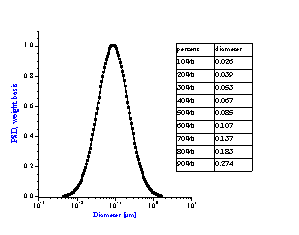
Figure 9A: Particle size distribution of slurry depends on chemical formulation.
Alumina slurry at pH 4 with zeta potential of +40 mV gives uni-modal distribution
corresponding to primary size of raw material.
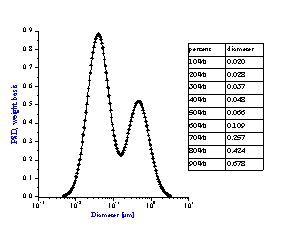
Figure 9B: Bimodal distribution resulting from aggregation of unstable
alumina slurry at pH 9 having zeta potential of only +5 mV.
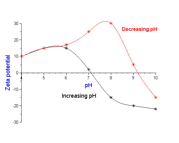
Figure 10: Slurry stability depends not only on chemical state but how one reaches this state.Titration of production
silicon nitride to low pH indicates high zeta potential and good stability at pH 7-8. However, process engineers found
that this pH did not provide good operating performance. Actual process included an acid wash of slurry. Back titration
to alkaline conditions shows dramatic shift in isoelectric point requiring shift in plant operating conditions. See text for details.